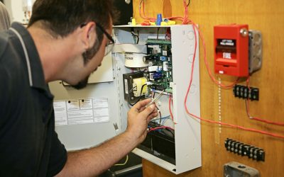
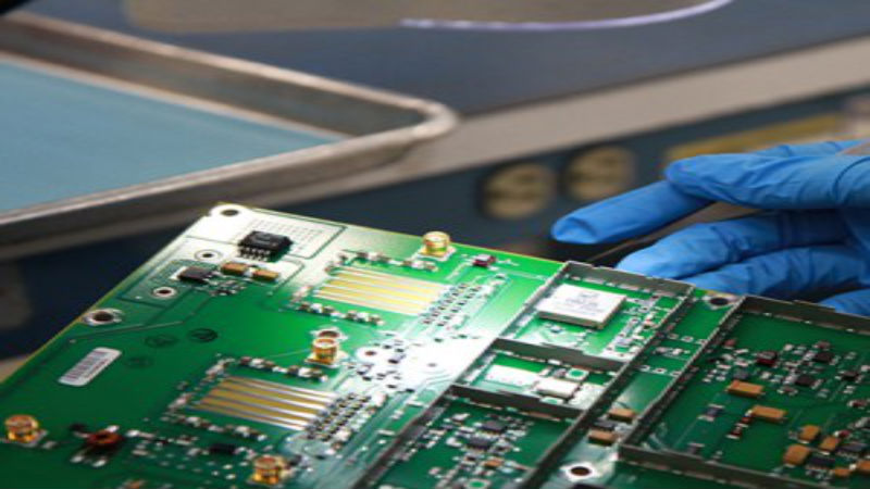
Control circuits are different than standard electrical circuits because they are used for tasks like motor control. They usually operate at much lower voltages than industrial equipment and machinery, because components are smaller and high voltages are not often needed. The industrial control transformer supplies these lower voltages and performs other vital tasks in the process of controlling equipment. Let’s explore the process a little closer to give you a better appreciation of this kind of equipment.
How Does an Industrial Control Transformer Work?
In many large applications, voltage is three phase and is commonly 120/208 or 277/480. The average commercial control circuit is designed to run on 110-120 volt single phase electricity. Transformers which lower voltage are known as “buck” transformers (as opposed to boost transformers which raise voltage). But how does this happen?
In order for electric voltage to be “transformed” it passes through two sets of coils in close proximity. For example, the first coil may have 500 ampere turns (this is how many times the wire is wrapped around a core). The second coil could have 250. Because there are 50 percent fewer ampere turns, the power coming in at 500 volts, would be cut in half to 250 volts. This is an oversimplification of the transformer principle but gives you a general idea of what happens.
Transformers are rated in volt-amps (VA). The higher the rating, the more equipment the transformer can handle.
Why Use an Industrial Control Transformer?
A transformer is the most efficient way to have a low voltage supply. Otherwise, you would need to run both single phase and three phase power. Industrial rated transformers are heavy duty and are better able to handle inrush current situations from contactors and starters. They are also designed to hold up under harsh conditions commonly found in manufacturing facilities.


